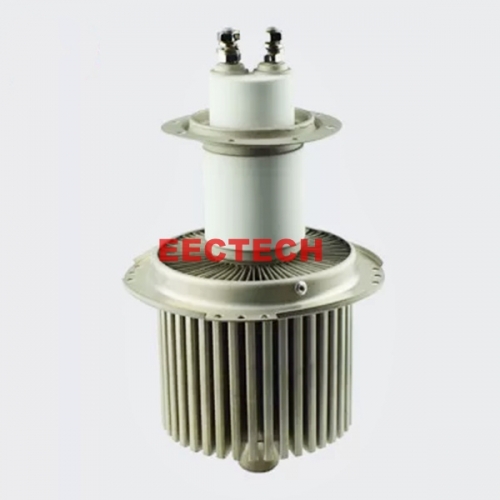
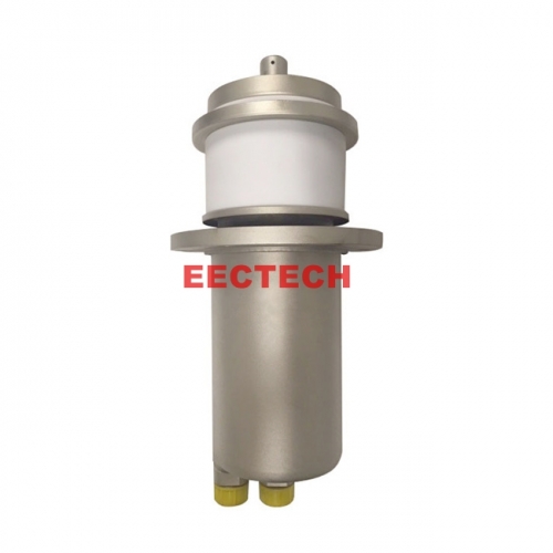
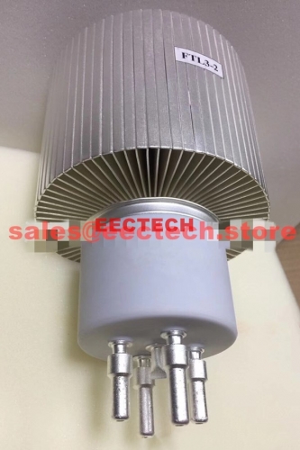
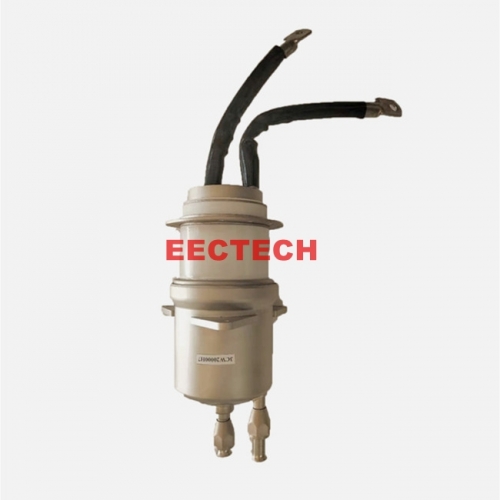
FU3124ZA electron tube, High-power cermet tetrode,equivalent to vacuum tube 4CV100000C, 8351, FD003Z tube, transmitter tube
ETT02012
The tube can be used for class C radio frequency amplification or oscillation, class A and B radio frequency linear amplification, class A and B push-pull audio amplification or modulation, and positive grid coherent class C radio frequency amplification
For fast delivery of goods, kindly please read following tips carefully before order:
Since this tube is high value and Customs declarance necessary,
for compliance with China foreigh exchange policy.
the Payment need to be paid through TT to our company bank account,
therefore, please DO NOT pay the order directly online.
please contact EECTECH through sales@eectech.store BEFORE order / BEFORE payment, we will help you to complete the order and payment fluently in a short time.Thank you.
Introduction:
1. FU3124ZA is a high-power cermet tetrode with thorium tungsten cathode and evaporative cooling anode. The maximum anode dissipation power can reach 100kW, and the maximum operating frequency is 30MHz.
2. The tube can be used for class C radio frequency amplification or oscillation, class A and B radio frequency linear amplification, class A and B push-pull audio amplification or modulation, and positive grid coherent class C radio frequency amplification
3. It can replace EIMAC's 4CV100000C tube on the 100kW step modulation (PSM) shortwave transmitter.
General characteristics
Electrical characteristics
Cathode…………………………………………Tungsten thorium cathode
Filament voltage………………………….…….…………........10V
Filament current……………………………………………… 300±10A
Transconductance…………………………………………160mA/V
Internal magnification factor……………………………… 4.5
Electrode capacitance:
Cathode and a grid………………………………170pF
Cathode and second grid…………………………………………18pF
Cathode and anode…………………………0.7pF
One grid and two grids………………………………300pF
A grid and anode………………………………2.7pF
Second grid and anode………………………………55pF
Mechanical properties
Stem……………………………..…………......Specially designed hierarchical ring
The highest temperature of the sealing area……………………………………200℃
The highest temperature of anode flange………………………………100℃
Working position………………………………..………………Axial vertical core column upward
Maximum height…………………………………………440mm
Maximum diameter……………………………………………………φ254mm
Maximum weight…………………………..……………….....33kg
cool down
Anode…………………………………………………… evaporative cooling
Core column, ceramic body………………………………..……………….. Forced air cooling
The minimum wind flow beside the core column………………………… 3.5m3/min
The minimum wind flow rate at the center hole at the bottom of the core column……………………0.1 m3/min
Allowable use limit
Anode DC voltage………………………………20 kV
Two-gate DC voltage………………………………2.5 kV
Anode DC current………………………………15 A
Anode dissipation power………………………………100 kW
Dissipated power of the second grid………………………………3 kW
One grid dissipation power…………………………………….……500 W
Working frequency………………………………30 MHz
Ambient temperature…………………………..…………45 ℃
Typical working state
Anode and grid joint modulation radio frequency power amplifier (working state of class C telephone)
Working frequency…………………………………………≤30 MHz
Anode DC voltage………………………………14 kV
Two-gate DC voltage………………………………750 V
One grid DC voltage……………………………………-700 V
Two-gate audio voltage peak value (100% modulation)………..….....750 V
Peak RF voltage………………………………1000 V
Anode DC current……………………………………9 A
Two-bar DC current………………………………………………2 A
One grid of direct current.......................................... 1 A
Grid excitation power…………………………1000 W
Anode dissipation power……………………………20 kW
Anode output power…………………………106 kW
Audio amplification or modulation (Class A and B working state single tube)
Anode DC voltage…………………………15 kV
Two-gate DC voltage………………………………1.5 kV
One grid DC voltage………………………………-360 V
Anode DC current at maximum signal.................................... 9.4 A
Anode DC current at zero signal……………………..……….…3 A
Two-bar DC current at maximum signal…………........……0.35 A
Peak audio excitation voltage.................................... 350 V
Excitation power……………………………………..……….…0 W
Load resistance (anode-cathode)…………………….……900 Ω
Anode dissipation power at maximum signal…………………………47.3 kW
Anode output power at maximum signal……………………93.7 kW
Note: 1. Transportation of electron tubes: electron tubes must be packed in a special shockproof packing box made by our factory Line transportation. Strictly prevent the packing box from being upside down or tilted. It is recommended to be transported by plane or bus. short During transportation, the road surface should not be inferior to the requirements of the tertiary road surface, and the speed should not exceed Over 30 km/h. When the load is insufficient, a counterweight should be added and the total weight should not be less than
40% of the truck's nominal load.
2. Storage of the electron tube: The electron tube must be placed vertically with the anode down and stored at a high room temperature In a dust-free with a relative humidity of no more than 80% at 5°C, do not go during storage Remove the protective cover of the ceramic ring to protect the surface of the electronic tube ceramic parts.
3. Inspection of the electronic tube: before and after unpacking the box, observe whether there are any abnormalities inside and outside the box
For delivery time:
Generally, we will dispatch the items within 30 days upon order confirmation; some items may need 60~90 days to get ready for delivery, then we will try our best to dispatch as soon as possible, or we will contact you and offer advice.
For Bulk order:
If you would like to place a bulk order, please contact us for better price and better delivery cost.