Introduce:
1.CX1836A is a high power metal-ceramic structure thyratron, which has the characteristics of high repeat frequency, fast ignition, low jitter, low drift, etc.
2.It can be used as high power pulse switch in radar, high-energy laser, high-energy accelerator.
3.CX1836A has three grids. It can be mounted and used according to the actual conditions of different applications, such as there’s a negative bias, one or multiple pulse triggers, etc.
Anode Parameters
Peak forward anode voltage: 50 kV max (note 1)
Peak inverse anode voltage: 10kV (note 2)
Peak current: 10kA max
Average anode current: 10A max
Rate of rise of anode current: 10kA/μs (note 3, 4)
Operating frequency: 50Hz~10k Hz(note 1, 5)
Gradient grid
Circuit connection: See picture
Trigger Pulse
Unload grid pulse voltage: 1000V~2000V
Pulse duration: 1μs min
Rate of rise of pulse: 10kV/μs min
Peak inverse voltage: 450V max
Unload grid negative bias: 0~-200V
Peak inverse current
Modulator connection: 5A~40A
Grid 3 serves as shield grid: 125A~175A(note 6)
Trigger delay: 0.5μs~3μs
Grid 1 (Pulse)
Unload grid pulse voltage: 600V~2000V
Pulse duration: 2μs min
Rate of rise of pulse: 1kV/μs min
Peak inverse voltage: 450V max
Current: 5A~100A
Grid 1 (DC)
Unload DC voltage: 75V~150V
Current: 0.25A~2.0A
Electrical Parameters
Cathode heater voltage: 6.3V±5%Vac
Cathode heater current: 80A~100A
Reservoir heater voltage: 6.3V±5%Vac
Reservoir heater current: 6.0A~8.0A
Preheating time: 10min(min)
Capacity between anode and gradient grid: 40pF
Capacity between gradient grid and grid 3: 40pF
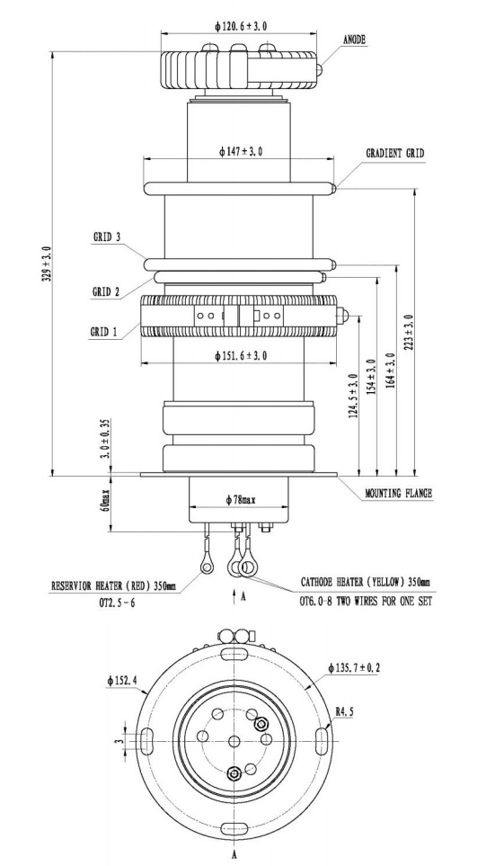
Mechanical Parameters
Mounting position: Flange Mounted (note 7)
Weight: About 11kg
Dimension: See outline
Cooling way: Forced-air (note 8)
Typical Parameters
Critical conduction anode voltage: 5000V max
Anode delay time: 350ns max
Anode delay time drift: 25 ns max
Time jitter: 10 ns max
Notes:
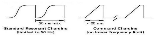
1. GL1836A has a shorter recovery time, but on the base of obtaining the grid design of high peak current
breaking capacity, thyratron’s high pressure resistance ability at low working frequency is limited. In order
to maximize thyratron’s performance, it's recommended that applying command charging technique to
limit the anode resistance time no more than 20ms.
2. Peak inverse anode voltage (include peak) must not exceed 10KV within 25μs after impulse current
discharge finished, otherwise it will damage the grid and cause spark inside the tube and shorten the
working life.
3. This rate of rise refers to that part of the leading edge of the pulse between 26% and 70% of the pulse
amplitude.
4. Under single narrow pulse working condition, rate of rise of the current can exceed 100kA/μs, finally
value greatly depend on the external circuit.
5. Maximum operating frequency depends on the external charge and discharge circuit, generally operating
frequency exceed 50Hz. Command charge circuit is recommended to ensure the thyratron is under
favorable working voltage.
6. In the case of Grid 3 is used as shield grid, it needs bigger trigger current than common connection mode
to conduct thyratron.
7. The tube must be mounted by means of its cathode mounting flange.
8. Air flow is no less than 7.1m(3)/min. The temperature of the envelope must not exceed the specified value:
Ceramic, anode and grids........................................150℃
Cathode mounting flange and base..........................120℃
Outline Drawing
 Schematic Diagram

R1 = 470Ω–1kΩ12W wirewound resistance;
R2 = 10–25 MΩ high voltage resistance, rated power is the same with peak forward anode voltage;
C1, Reservoir protection capacitor, 1000pF low inductance capacitor, voltage rating≥500V;
C2, Reservoir protection capacitor, 1μF, voltage rating≥500V;
C3 = 500–1000 pF capacitor, voltage level matches with peak forward anode voltage;
Trigger connection
1. The modulator has two trigger pulses with negative bias, which is recommended to use, it can maximize
the performance of the cathode and effectively guarantee a long service life.
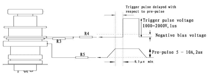
R3 = 100Ω12W wirewound resistance;
R4 = 12W wirewound resistance, matches with drive current;
R5 = 12W wirewound resistance, matches with drive current;
2. The modulator only has a single pulse triggering
a) Pulse triggering without negative bias
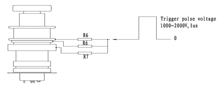
R6 = 1.8 kΩ12W wirewound resistance;
R7 = 47Ω12W wirewound resistance;
b) Pulse triggering with negative bias
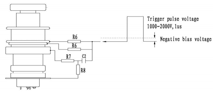
R6 = 1.8 kΩ12W wirewound resistance;
R7 = 47Ω12W wirewound resistance;
R8 = 10kΩ12W wirewound resistance;
C2 = 0.01mF–0.1mF coupling capacitor;
3. The modulator has a single pulse triggering (with or without negative bias) and DC pretrigger It applies only to the applications with rate of rise of anode current ≤10kA/μs and anode current under 40kV;
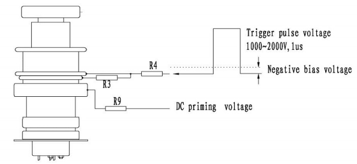
R3 = 100Ω12W wirewound resistance;
R4 = 12W wirewound resistance, matches with drive current;
R9= 12W wirewound resistance, matches with drive current of Grid 1;
4. Command charging, Grid 3 serves as shield grid
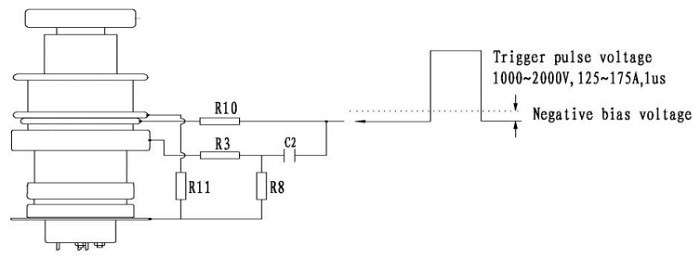
R3 = 100Ω12W wirewound resistance;
R8 = 10kΩ12W wirewound resistance;
C2 = 0.01mF–0.1mF coupling capacitor;
R10 = 12W wirewound resistance, matches with grid pulse current with a range of 5–16Ω;
R11= 1Ω–10Ω, depending on the extent to which the shield is needed; 12W wirewound resistance or resistance wire (>10 W);
For delivery time:
Generally, we will dispatch the items within 10 days upon order confirmation; some items may need 20~30 days to get ready for delivery, then we will try our best to dispatch as soon as possible, or we will contact you and offer advice.
For Bulk order:
If you would like to place a bulk order, please contact us for better price and better delivery cost.
 USD
USD EUR
EUR GBP
GBP