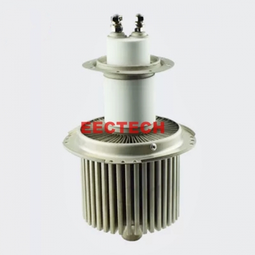
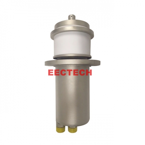
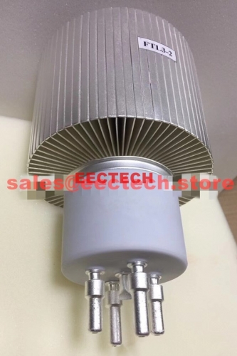
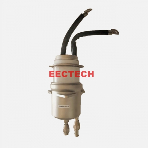
CX1159 Thyratrons,EECTECH thyratrons,Equivalent to E2V CX1140LE
Thyratrons use deuterium as arc discharge dielectric,which have the advantages of high working voltage,high pulse current,quick and steady fire lighting,low trigger voltage,high efficiency,long life,light weigh,small size,easy for
Application:
thyratrons are widely used in scientific research,medical treatment and industry such fields,which include laser instruments,radar,pulse modulator,medical linear accelerator,tommy bar protection and other electric instruments and equipments.
Anode Characteristics
Peak Forward Anode Voltage: 33kV max [1]
Peak Anode Voltage: 33kV max [2]
Peak Forward Anode Current: 1000A
Average Anode Current:
Continuous operation: 1.25A max
Intermittent operation: 2.2 A max
Anode Current Rate of Rise: 5kA/μs [3]
Grid 2 Drive
Unloaded Drive Pulse Voltage: 500V~1000V
Driver Circuit Output Impedance: 50Ω~ 500Ω
Rate of rise of grid 2 pulse: 1kV/μs min [3]
Driver Pulse Duration: 1 μs min
Loaded Grid 2 Bias Voltage: 0 V~ -150 V
Grid 2 Pulse Delay: 0.5μs ~ 3μs
Peak Inverse Grid 2 Voltage: 450V max
Grid 1 Pulse Drive
Unload Grid 1 Drive Pulse Voltage: 300V ~ 1000V [4]
Peak Grid 1 Drive Current: 0.3A~ 1A [5]
Grid 1 Pulse Duration: 2us min
Rate of Rise of Grid 1 Pulse: 1kV/us min [3]
Peak Inverse Grid 1 Voltage: 450V max
Grid 1 DC Drive
DC Grid 1Unloaded Priming Voltage: 75V~ 150V
DC Grid 1 Priming Current: 50mA ~ 100 mA
Electrical
Cathode Heater Voltage: 6.3±5%V
Cathode Heater Current (6.3V): 20A~25A
Preheating Time: 10 min.
Mechanical
Outline and Dimension: See outline drawing
Net weight: About 1500g
Mounting Position: Pin [6]
Cooling Way: Natural or forced-air cooling [7]
Characteristics
Critical anode voltage for conduction: 2.0 kV max
Anode Delay Time: 250ns max [8]
Anode Delay Time Drift: 50ns max [9]
Time Jitter: 5ns max
Notes:
[1] It is the maximum peak voltage under the condition of resonant charging.
[2] Peak inverse anode voltage (include peak) must not exceed 10KV within 25 μs after impulse
current discharge finished, otherwise it will damage the grid and cause spark inside the tube and
shorten the working life.
[3] This rate of rise refers to that part of the leading edge of the pulse between 26% and 70% of the
pulse amplitude.
[4] Measured with respect to cathode. Pre-pulsing of grid 1 is recommended for high rate of rise of
current applications.
[5] The higher grid 1 is pulsed, the larger must the grid 2 negative bias be, to prevent the tube firing on
the grid 1 pulse.
[6] The tube must be fitted using its corresponding 5-pin board.
[7] If the tube is cooled by forced-air, an air flow of at least 2.83 m3
/min is required.
[8] The time interval between the instant at which the rising unloaded grid 2 pulse reaches 26% of its
pulse amplitude and the instant when anode conduction takes place.
[9] Anode firing delay time drift, the drift in delay time over a period from 10 seconds to 10 minutes
after reaching full voltage, its anode firing delays time of change.
Electrodes Connection Schematic Diagram:
Outline Drawing:
For delivery time:
Generally, we will dispatch the items within 10 days upon order confirmation; some items may need 20~30 days to get ready for delivery, then we will try our best to dispatch as soon as possible, or we will contact you and offer advice.
For Bulk order:
If you would like to place a bulk order, please contact us for better price and better delivery cost.